Concepts
Coordinate systems are a fundamental concept associated with spatial data. When mapping the Earth's terrain and natural and cultural features, it is important that all mapped objects be accurately located with respect to an accepted geographic frame of reference. This is particularly important when spatial data from multiple sources are being integrated. If any of the spatial data sets are not accurately defined in an accepted frame of reference, then gaps overlap, and mismatches will occur. Several reference systems include geodetic, geocentric, and map projection.
Geodetic coordinates, for specifying point locations relative to the Earth's surface, are latitude, longitude and height. These coordinates all depend upon a reference ellipsoid for their basis. Latitude and longitude are horizontal components, while the vertical component is height.
Geocentric coordinates are three-dimensional x,y,z Cartesian systems that provide an Earth-centered definition of position, independent of any reference surface. This system has its x,y plane in the plane of the equator with the z-axis extending through the north pole. This system is not frequently used in general cartography.
Maps are representations of the Earth’s surface on a flat, two-dimensional surface such as a sheet of paper or a computer display. It is impossible to represent a curved shape to a two-dimensional medium without distortion. Map projections are created to accomplish this with a carefully defined and understood amount of distortion. A map projection can preserve some properties at the expense of other properties, but not all of them simultaneously. Distortions of conformality, distance, direction, scale, or area always result from map projections. The main properties of map projections are listed below.
PROJECTION PROPERTIES
Conformal: The scale at any point on the map is the same in all directions. Meridians (lines of longitude) and parallels (lines of latitude) intersect at right angles. It preserves the shape of areas.
Equal area: This refers to the ratio between the area on the map and the area on the Earth. A constant proportion between areas on the map and ground can be made possible by compensating the scale so that it varies across the map
Equidistant: Equidistant maps show true distances (or correct scale) only from the centre of the projection or along with a special set of lines.
True Direction (azimuthal): A map preserves direction when azimuths (angles from a point on a line to another point) are portrayed correctly in all directions.
Perspective: some azimuthal projections are true perspective, that is to say, they can be constructed mechanically, projecting the surface of the Earth by extending lines from a point of perspective onto the plane.
Compromise: some projections offer a compromise of several properties (e.g. the projection Equidistant Conic is not conformal, perspective, or equal area, but a compromise between Lambert Conformal Conic and Albers Equal Area Conic).
Straight Rhumb: A rhumb line is a line on the surface of the Earth cutting all meridians at the same angle. A rhumb line shows true direction. Parallels and meridians, which also maintain constant true directions, may be considered special cases of the rhumb line. A rhumb line is a straight line on a Mercator projection. A straight rhumb line does not show the shorter distance between points unless the points are on the Equator or on the same meridian.
Some other map properties related to the projection are:
- Scale: The relationship between a distance portrayed on a map and the same distance on the Earth.
- Accuracy: Depending on how much of the Earth is being mapped and how the distortion is arranged. If it is a small region of the Earth’s surface, the curvature is slight and therefore a slight scale distortion will result. A cartographer must place more accurate distances where they are most important to the user or to the purpose of the map. The coverage scale and maximum scale error (greatest departure from 1.0) are factors to be considered.
PROJECTION CATEGORIES
 Azimuthal Projection: The result of projecting a spherical surface onto a plane. In an azimuthal projection, a flat sheet of paper is tangent to the globe at one point. The point light source may be located at the globe’s centre (gnomonic projection), on the globe’s surface directly opposite the tangent point (stereographic or perspective projection), or at some other point along the line defined by the tangent point and the centre of the globe, e.g., at a point infinitely distant (orthographic projection). In all azimuthal projections, the tangent point is the central point of a circular map; all great circles passing through the central point are straight lines, and all directions from the central point are accurate. If the central point is a pole, then the meridians (great circles) radiate from that point and parallels are shown as concentric circles. The gnomonic projection has the useful property that all great circles (not just those that pass through the central point) appear as straight lines; conversely, all straight lines drawn on it are great circles.
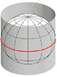 Cylindrical Projection: The result of projecting a spherical surface onto a cylinder. In a typical cylindrical projection, one imagines the paper to be wrapped as a cylinder around the globe, tangent to it along the equator. Light comes from a point source at the centre of the globe or, in some cases, from a filament running from pole to pole along the globe’s axis. In the former case, the poles clearly cannot be shown on the map, as they would be projected along the axis of the cylinder out to infinity. In the latter case, the poles become lines forming the top and bottom edges of the map. The Mercator projection, long popular but now less so, is a cylindrical projection of the latter type that can be constructed only mathematically. In all cylindrical projections the meridians of longitude, which on the globe converge at the poles, are parallel to one another; in the Mercator projection the parallels of latitude, which on the globe are equal distances apart, are drawn with increasing separation as their distance from the equator increases in order to preserve shapes. However, the price paid for preserving shapes is that areas are exaggerated with increasing distance from the equator. The effect is most pronounced near the poles; E.g., Greenland is shown with enormously exaggerated size although its shape in small sections is preserved. The poles themselves cannot be shown on the Mercator projection.
Conic Projection: The result of projecting a spherical surface onto a cone. In a conic projection, a paper cone is placed on a globe like a hat, tangent to it at some parallel, and a point source of light at the centre of the globe projects the surface features onto the cone. The cone is then cut along a convenient meridian and unfolded into a flat surface in the shape of a circle with a sector missing. All parallels are arcs of circles with a pole (the apex of the original cone) as their common centre, and meridians appear as straight lines converging toward this same point.
Some conic projections are conformal (shape preserving); some are equal-area (size preserving). A polyconic projection uses various cones tangent to the globe at different parallels. Parallels on the map are arcs of circles but are not concentric.
Miscellaneous Projections: There is a large set of projections that are modifications of the other three traditional groups. For example, the Sinusoidal is called a pseudocylindrical projection because all lines of latitude are straight and parallel, and all meridians are equally spaced. However, it is not a truly cylindrical projection because all meridians except the central meridian are curved. Another type of projection is called lenticular (lens-shaped), where meridians and parallels curve toward the poles and maintain or decrease their distances from each other going from the centre to the edges of the map. Many other useful types of projections are difficult to categorize and can be called simply miscellaneous (some can be named pseudo azimuthal, polyconic, polycylindrical, pseudoconic, and so on.)
DATUMS AND ELLIPSOIDS OVERVIEW
An ellipsoid is a mathematical object generated by the revolution of an ellipse about one of its axes. The Earth is not a sphere but an ellipsoid distorted by rotation about its axis, with the globe bulging at the equator and flattened at the poles. The actual amount of the flattening is approximately 21.5 km difference between the polar and equatorial radii. Ellipsoidal Earth models are required for accurate range and bearing calculations over long distances. For example, GPS navigation receivers use ellipsoidal Earth models to compute position and waypoint information. Ellipsoidal models define an ellipsoid with an equatorial radius and a polar radius. The best of these models can represent the shape of the Earth over the smoothed, averaged sea surface to within about 100 metres.
Reference Ellipsoids are usually defined by semi-major (equatorial radius) and flattening (the relationship between equatorial and polar radii). Other reference ellipsoid parameters such as semi-minor (polar radius) and eccentricity can be computed from these terms.
A datum is a mathematical model that describes the shape of the ellipsoid, and the orientation of coordinate systems used to map the Earth. Historically a series of control points are used to build the mathematical model that best fits the Earth shape locally. Different nations and agencies use different datums as the basis for coordinate systems in GIS.
Modern datums range from flat-Earth models used for plane surveying to complex models used for international applications which completely describe the size, shape, orientation, gravity field, and angular velocity of the Earth.
Datum Examples
- NAD27: For many years the North American Datum of 1927 was the standard in the United States. NAD27 was based on the Clarke Ellipsoid of 1866, which was developed from a ground survey in Europe and North America in the 19th Century. The centre point for NAD27 is Meades Ranch in Kansas, USA.
- NAD83: During the 1970s and 1980’s satellites were able to measure the ellipsoid flattening more accurately (the World Geodetic System ellipsoid of 1984 or WGS84) and a new datum was developed from these measurements called the North American Datum of 1983. The Global Positioning System is based on WGS84. The centre point for NAD83 is the centre of the Earth’s mass and uses the GRS80 spheroid which factors in the Earth’s equatorial bulge.
MAP SCALE
A map scale is the ratio of the distance on the map face and the actual real-world ground distance. The scale ratio is commonly referred to as a representative fraction—one unit on the map is equal to x units on the Earth.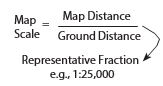
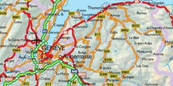
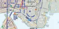
A large scale map (e.g. 1:10,000) covers a smaller portion of the Earth. It will have more detail and in effect, it is zoomed in on an area (like a city). A small scale map (e.g. 1:1,000,000) covers a larger area of the Earth. On a small scale, map features appear to be smaller, as the map is in effect zoomed out (to view a
country). The effectiveness of the scale determines how successful the map is in communicating the desired information to the user.
Large scale map Small scale map
|
Features are larger |
Features are smaller |
|
More detail |
Less detail |
| Covers a smaller geographic area | Covers a larger geographic area |
| More variety in map content | Less variety in map content |
| Less generalization of features | More generalization of map features |
Common Coordinate Systems Classes
The two types of coordinate systems supported by MAPublisher and Geographic Imager are geodetic and projected systems:
- Geodetic systems are described below in detail.
- There are almost limitless ways to define a projected system, they are based on a projection (i.e. mathematics formulas) and associated parameters. Each projection and set of parameters creates a different "projected system". Please see the Supported Projections to see which projections we currently support — users can create custom systems by entering their own parameters, or use the pre-defined coordinate systems provided in the Geodetic Data Source (see Appendix 2 of MAPublisher User Guide and Chapter 4 of Geographic Imager User Guide). Two common projected coordinate systems classes are the Universal Transverse Mercator system and US State Plane. Both are described here.
GEODETIC
A geodetic coordinate system is a three-dimensional coordinate system defined by an ellipsoid, the equatorial plane of the ellipsoid and a plane defined along the polar axis (a meridional plane).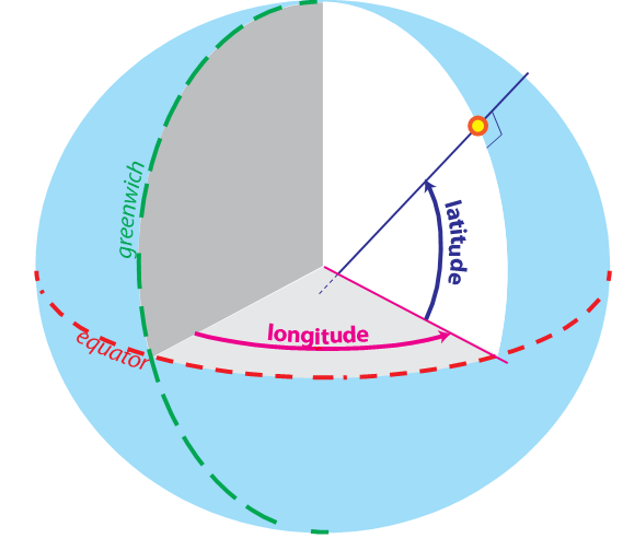
Coordinates in a Geodetic Coordinate System are given by a geodetic latitude (the angle between the normal to the ellipsoid at a location and the equatorial plane), a geodetic longitude (the angle between the meridional reference plane and a meridional plane containing the normal to the ellipsoid at a location) and a geodetic height (the perpendicular distance of a location from the ellipsoid).
A geodetic datum is the only required defining parameter for a Geodetic Coordinate System in MAPublisher and Geographic Imager. A geodetic datum defines constants that relate a Geodetic Coordinate System to the physical Earth, the dimensions of the reference ellipsoid, the location of the origin of the system, and the orientation of the system.
A geodetic coordinate is specified in MAPublisher or Geographic Imager by latitude, longitude, and ellipsoidal height values. Any angular unit defined may be used to specify latitude and longitude coordinates.
The ellipsoidal height of a location is defined as the elevation of the location above the geoid (essentially a modelled surface representing mean sea level) and the separation of the geoid surface from the ellipsoidal surface. MAPublisher and Geographic Imager assume a value of 0.0 if the ellipsoidal height of a location is unknown. Any distance unit defined may be used to specify ellipsoidal height values.
PROJECTED: UNIVERSAL TRANSVERSE MERCATOR
The Universal Transverse Mercator (UTM) system is an international system developed by the U.S. Army Corps of Engineers in the 1940s. This system extends around the globe from 84 degrees north to 80 degrees south and divides the world into 60 zones in the Northern Hemisphere and 60 corresponding zones in the southern hemisphere. Each zone covers six degrees of longitude. Each zone extends three degrees eastward and three degrees westward from its central meridian. Zones are numbered west to east from the 180-degree meridian.
Note: A map of the UTM zones is provided in the Appendix of this guide.
Each UTM zone uses a different coordinate system as a reference. All of them are based on the Transverse Mercator projection, but with a different Central Meridian parameter (the False Easting and False Northing parameters may also vary).
In MAPublisher and Geographic Imager, the coordinate system definition of each zone can be found in the Specify Coordinate System dialog box under Coordinate Systems > Projected > UTM. Different versions of each UTM zone coordinate system can be found in subfolders organized by base geodetic datum and distance unit.
The standard unit of the UTM system is the metre, and the most commonly used geodetic base is WGS84. These definitions are found under Coordinate Systems > Projected > UTM > WGS84, the coordinate system names match the zone names and extents — e.g. UTM zone 10N (126W to 120W).
PROJECTED: US STATE PLANE
The "State Plane Coordinate System" (SPCS) convention divides all fifty states of the United States, Puerto Rico and the U.S. Virgin Islands into over 120 numbered sections, referred to as zones. Each zone has an assigned projected coordinate system defined by a projection and its parameters for the region. Each zone coordinate system can be found in the MAPublisher and Geographic Imager library.
There are four projections for SPCS. The geometric direction of each state determines the projection utilized. For states that are longer in the east-west direction, the Lambert Conformal Conic is used. States which are longer in the north-south direction use the Transverse Mercator projection. The panhandle of Alaska, which has the sole distinction of lying at an angle, garners the use of the Oblique Mercator projection, while Guam uses a Polyconic projection.
Zone boundaries follow state and county lines and because each zone is small, distortion is less than one in 10,000. Each zone has a centrally located origin and a central meridian that passes through the origin. The United States uses a two-zone numbering system: The United States Geological Survey (USGS) code system and the National Ocean Service (NOS) code system. However, other code systems do exist.
Note: A map of the US State Plane zones is provided in Appendix of this guide.
There are two sets of State Plane coordinate systems defined in the United States, one based on the North American Datum of 1927 and the other based on the North American Datum of 1983. The U.S. Survey Foot is the standard unit in the State Plane coordinate system of 1927. The metre is the standard unit in the State Plane Coordinate System of 1983.
In the MAPublisher and Geographic Imager coordinate systems library, the different versions of the US State Plane system can be found in the folder Coordinate Systems > North America > United States:
- The US State Plane NAD27 folder contains the coordinate system definition for each zone (sorted by zone name) - for each coordinate system, the distance unit is set to US foot.
- The US State Plane NAD83 folder contains sub-categories for each different version of the system: different units, or NAD83 versions. The most common versions used are in NAD83 (Meters) or NAD83 (US Feet). In all cases, the coordinate system definitions are sorted by zone name.
Comments
0 comments
Please sign in to leave a comment.